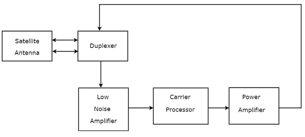
C Band Satellite Transponder Block Diagram

Explain The Block Diagram Of C Band And Ku Band Transponder With The Help Of Block Diagram

Schematic Diagram Of Multi Band Satellite Transponder Unit Ofc Download Scientific Diagram

C Band Adaptive Small Satellite Transponder Download Scientific Diagram
Satellite Communication Transponders Tutorialspoint

C Band Sats Part 1 Introduction To Satellite Hunting Gough S Tech Zone

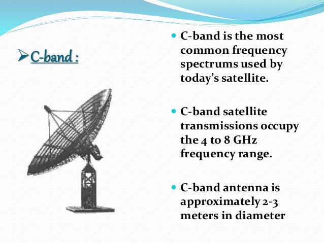
C Band Microwave Frequency Band
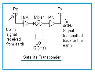
A block diagram of a transponder.
C band satellite transponder block diagram.

C Band An Overview Sciencedirect Topics
Satellite Lnb What Is It How Does It Work And Where Do I Buy One

C Band Geo Satellite Link Budget In Clear Air Download Table

Ltcc Based Multi Chip Modules At C Band And Ka Band For Satellite Payloads Semantic Scholar

Installation And Setup Of A Direct Focus Satellite Antenna Of C Band Reception Of The Yamal Satellite 401 90e
Http Licensing Fcc Gov Myibfs Download Do Attachment Key 136046

Hy 2a Eoportal Directory Satellite Missions

Hylas Eoportal Directory Satellite Missions
Transponder Vs Repeater Difference Between Transponder And Repeater

What Is Transponder Explain Single Conversion Transponder
Http Www Jetir Org Papers Jetir1707038 Pdf

Satellite Communications Ppt Video Online Download
Mil Satcom Capacity Crunch The Buc Stops Here

M3msat Eoportal Directory Satellite Missions

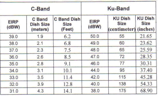
Understanding The Difference Between Ku Band And C Band Frequencies Techsawa

L Band An Overview Sciencedirect Topics

What Is C Band Extended C Band And Ku Bands Trackdish Com In 2020 Ku Band Satellite Phone Band

Fedsat Eoportal Directory Satellite Missions
Https Encrypted Tbn0 Gstatic Com Images Q Tbn 3aand9gcsxh9ws27upanxugmycedovf6zrljxnk69jxmdnuc4l W5k0i8t Usqp Cau

Himawari 8 And 9 Satellite Missions Eoportal Directory

Pdf 4 8 Ghz Lna Design For A Highly Adaptive Small Satellite Transponder Using Ingaas Phemt Technology
Satellite Communication
Kings Corner For C Ku Band On A Small 1 2 Meter Dish Archive Through July 10 2008 Ecoustics Com

Intelsat S A And Ses S A To The Moon Nasdaq
Source : pinterest.com
